5 Toggle Switch
Array
(Model #2060)

Best Viewed at 1024 by 768 Resolution
Desktop Aviator
HOME

Click HERE for
a LOOK at
Our $$$ SAVING eBay Auctions.

I Accept Credit
Cards Through:

PAYPAL
If you have any
comments or need additional information on the use of the
Toggle Switch Array Panel,
please write me
at:
Wiring the Switch Array to our 2040
Digital Interface
The Switch Array was designed to
operate with our Model 2050 USB Junction
Box, but with a bit of effort and some electronics
knowledge, the Array can also be used with the USB to 20 Button
INTERFACE (Model 2040 - see above). As its name
implys, the 2040 allows you easily connect up to 20 digital switch
circuits to your USB Port.
They say that "A picture is worth a
thousand words", so here is a diagram to show you how to wire up two
Toggle Switch Array Panels to the USB Interface. If you wish to wire only
one Switch Array, just connect the 5 RCA outputs to J1 - 2, 4, 6, 8, 10
(the First 5 Red Dots seen below)
Wiring for the
Do-it-Yourselfers
Above is a photo of the backside of
the 2060 Panel. As you can see, the RCA Jacks are labeled as follows (from
Left to Right): +5VDC Power - Toggle Switch #1 - Togle Switch #2 - Toggle Switch #2 -
Toggle Switch #4 - Toggle Switch #5
COMMON GROUND to ALL Switches is the
Outter Casing of the RCA Jacks (This is where the Power Supply GND is
Connected).
To test the 2060 for operation, it
would be easier if you connect an RCA Cable to the Power Terminal on the
Panel. When the cable is in place, apply +5 Volts DC to the indicated RCA
Jack (see above). The outside casing is the power supply's GND connection.
Now, using a VOM (Voltmeter set to it's 10 volt Scale), take the "BLACK"
lead and connect it to your Power Supply GND Connection. The "RED" lead is
touching the Glass Diode at the point where it is soldered to the PCB
(This is the BANDED End). You will see a +5V for each of the 5 Diodes.
NOTE: If you touch the
VOM's "RED" Lead directly to the center terminal of the RCA Jack, you will
not see any voltage readings on the Meter. This DOES NOT indicate a
malfunction of the panel. This is because the Diode Blocks the voltage (A
diode is a device that allows voltage to pass in ONLY ONE direction). In
the 2060, the diode BLOCKS the +5 volts from passing to each RCA Jack,
but does allow a Ground to pass. This Ground is the Control Pulse
that is needed by our USB Junction Box and our Model 2040 USB
Interface.
Again, with the "RED" Lead touching
the BANDED end of the Diode (X1), you will see a +5V on your Meter. Now,
flip SW1. You will see this +5V go to 0 voltage (Ground) then back up to
+5V again. This Pulsing action will take about 1/4 second. Flip SW1 again.
As before, the +5V will once again go to Ground, then back to +5V in about
1/4 second.
Perform the same test with the
remaining 4 Toggle Switches. The "Grounding Pulse" will be
present.
To have your computer sense these
Pulses, you would need to design your own USB Circuit that "sees" this
pulse and passes it along to your computer for subsequent programming by
your Flight Simulator. Or the 2060 can be plugged our Model 2050 Junction
Box (the BEST Choice for the
Flight Simmers with little or no electronic background) or wired to our
Model 2040 USB to 20
Button INTERFACE (see
above).
Wiring YOUR Toggles
Switches
If you purchased the 2060 less
the 5 mini toggle switches, it is very easy to wire your own switches
in their places. Below is a diagram showing two of the
five
toggle switch locations on the 2060
pirnted circuit board ( J1 - J2 - J3 - J4 - J5 ). Notice the small white
rectangular boxs labeled A - B & C. These holes
are
connected in parallel to the larger
holes (immediately to the right). It is these holes where you solder the
three wires connecting your Toggle Switches to the
2060 board.
The CENTER Terminal of the
five Toggle Switches is soldered to each "B" hole on the PC Board.
The TOP Terminal is soldered to hole "A"; while the
remaining toggle switch terminal is
soldered to hold "C". Any type of SPDT (Single Pole Double Throw) toggle
switch can be used with the 2060. The length
of the wire connecting the toggle
switch to the 2060 PC Board has been tested up to 15 inches in
length.
Connecting
the 2060 to Our USB Junction Box (Model 2050)
Connecting the USB Junction Box
to your computer is a simple matter. Find an unused USB Port on your
computer
and plug in the Junction Box.
When pluged in, your computer will start to look for and load the required
Driver
Software. A small window in the
lower right hand corner of the screen will indicate that New Hardware was
found.
When the Driver software is
loaded, you can click on the "START" icon (lower left hand corner of the
screen). Then
click on "Control Panel". Then
"Game Controllers". When clicked, you should see something similar to the
photo
shown
below.
The Junction Box is displayed as:
"USB Junction Box Model 2050". Using your Mouse, Highlight this text and
click.
A new window will appear as shown
above. Here you can see 24 RED Buttons indicating a Digital Switch Input.
The
Junction Box is designed for 20
Inputs. So disregard the last 4 Buttons.
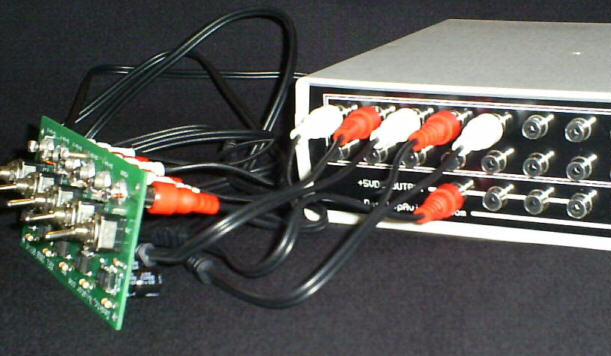
The photo below shows how you can
easily connect the Switch Array to our Model 2050 USB Junction Box. Using
3
Dual RCA Cables (You can purchase these from Desktop
Aviator - 3 Needed) , plug 5 of the 6 cables to Switch 1 to Switch 5 of
the Switch Array. The other
side of the same cables are then connected to any of the available RCA
jacks on the 2050.
The 6th Cable delivers the needed
voltage to power the Switch Array. Connect this cable to any of the 4
available
"+5VDC Output" jacks on the 2050.
The other side is connected to the "POWER" jack on the Switch
Array.
Depending where you connect the RCA
Cables from the Switch Array to the Junction Box; anyone of the 20
Buttons
will light when you flip the Toggle
Switch. Flip all 5 Switches to verify that 5 RED Buttons will light when
the Toggle
is flipped. The RED Button will light
for about 1/4 second. This is Normal.
If you purchased 2,3 or even 4 Toggle
Switch Arrays, just plug the RCA Cables into any available RCA Jack on
the
Junction Box. BUT REMEMBER: The Four RCA Jacks on the Bottom Row of the Junction Box
delivers +5VDC and
should NOT be connected
to ANY Toggle, Spring Return Switch, ect. that places a short on these
jacks. If anyone
of these Jacks are
shorted to GROUND, you might damage your computer's Power
Supply.
We at Desktop Aviator have developed
a number of Add-on Modules that can be easily connected to the
Junction Box. Using the Junction Box
will allow you to add a:
Other Add-on devices are to be
added to this list in the near future.
This Page is Still Under
Construction! MORE to Come!
HAPPY FLYING!
Purchasing Informationfor the Model 2060, can be found at: