|
HOW TO BUILD A
PUSH PULL THROTTLE QUADRANT
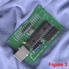
USB ANALOG INTERFACE The most efficient way to interface the 1090 Slide Assembly to your computer is using the USB Port. For this to happen, we need some sort of device that reads data from the Slide Assembly and converts it into an Digital data stream in a form and resolution for the computer to handle. So in-steps the Model 2097 (http://www.desktopaviator.com/Products/Model_2097/index.htm). The 2097 is a modified version of Desktop Aviator’s popular 2090 Encoder Board (http://www.desktopaviator.com/Products/Model_2090/index.htm - More on that board in a future article). The 2097 is a small circuit board that easily connects up to eight Rotary and or Slide Potentiometers to your computer, using a 10-bit Resolution. It easily plugs into an available USB Port. It also provides 4 Digital Inputs thus allowing you to add a toggle or push button switch that can be assigned as Flaps, Landing Gear (Up/Down), Fuel Tank Select, Parking Brake, Carb Heat ect.
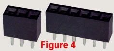
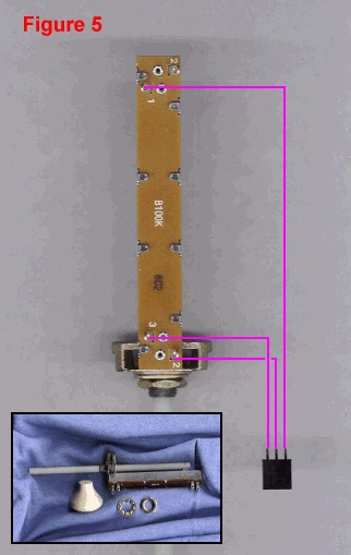
WIRING THE SLIDE POTS With your purchase of the 2097, you will also receive eight 3-pin female connectors and one 6 pin connector (Fig 4). These connectors provide the easiest way to connect the slide assemblies and toggle switches to the 2097. Figure 5 shows the underside of the 1090 Slide Assemble. Note there are 4 terminals; two of which are numbered the same. The two #2s indicate that these terminals are connected internally but can output different resistance values. For the wiring of our Throttle Quadrant, we will use the #2 terminal that is the closest to the mounting hub. As seen in Fig 5, solder a length of wire from the #2 terminal of the Slide Assemble (the one closest to the mounting hub) and connect it to the Center Terminal of one of the 3-pin Female connectors. The #1 Slide Terminal is soldered to one of the outside terminals of the 3-pin connector and terminal #3 of the slide is soldered to the remaining terminal on the 3-pin connector. At this time, the only critical connection is the #2 terminal on the slide; make sure its soldered to the center terminal on the 3-pin connector. Try to keep the length of these wires to less then 15 inches. Longer wires might introduce “hum” into the USB Adapter and cause erratic operation of the slide.
Depending on which Cessna model you are building, you will need at least 2 Slide Assemblies. For the Skyhawk; 2 Assemblies are required; one for the Throttle and the second for Fuel Mix; while the Cessna Skylane requires three Assemblies; one for Throttle, the second for Fuel Mix and the third for Propeller Pitch.
MOUNTING THE SLIDE ASSEMBLIES
If you are planning on mounting the Slide Assemblies inside your own panel, it must be less then ¼ inch thick. The mounting hubs on the Assemblies cannot be used on any panel with a thickness more then ¼ inch. CONNECTING THE SLIDE ASSEMBLIES TO THE 2097 BOARD
If you are anxious to see your Throttle Quadrant work, just plug the 2097 board into your computer’s USB Port; power-up then get into the “Game Controllers” window. Clicking on “USB Adapter” will display the window seen in Figure 8. Slide all assemblies in then out and observe the RED Calibration Bars move up and down. This would also a good time to calibrate the Throttle Quadrant by clicking on “Settings” then “Calibrate”. If you need some additional help in calibrating your Throttle you can goto: https://desktopaviator2.tripod.com/Instructions/Throttle/HiR/index.htm . Here you will have complete and accurate instructions on calibrating your Throttle. If you find that while activating the slide assemblies, the Calibration Bars for each is not in synchronization (All Bars UP with the slides push all the way in), just take the 3 pin connector from the offending slide and reverse it on the 2097 board.
PAINTING & INSTALLING THE KNOBS With your purchase of the Slide Assemblies, you will also receive a wooden knob. The knobs need to be drilled with a ¼ inch hole so that they can be pushed over the plastic rod on the slide assembly. But before installing the knobs; they need to be painted. To distinguish the different functions of the assemblies, we need to paint the knobs in the standard Black – Blue – Red format. Black being the Throttle control; Blue is used to adjust the Prop Pitch; while the Red controls the Fuel Mixture. I find using a soft sponge dipped into the appropriate color will give very good results. When dried, the knobs should be painted with some sort of lacquer for protection. When dry, press the knobs on the appropriate slide assembly.
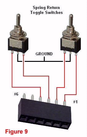
ADDING SWITCHES The 2097 allows you to connect 4 switches. These switches can be programmed to any switch function you need. For this short article, lets concentrate on wiring two Toggle switches to the 2097; one for Flaps and the second for the Landing Gear. A word about the Toggle Switches. A standard ON/OFF switch should not be used for the Flaps Control; rather a Switch that has a Spring Return – Center Off type (Momentary /Off/ Momentary). This Toggle Switch can be found at: http://www.mpja.com/prodinfo.asp?number=16085+SW for about $1.00. This switch can also be used for your Landing Gear control.
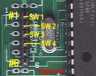
Figure 9 shows how you can wire the toggle switches to the 6 pin female connector. You may have noticed by now, we are using the first 4 pins of the 6 available. The last two pins are not used. Just take the wired 6 pin connector and plug it into the Male header connector on the 2097 board (Fig 10).
Again, these connections can be tested by going into the Calibration Window. Flip each Toggle switch and take note of the lighting of the small Red dots. When operating correctly, you can now assign the needed functions using your Flight Simulator program.
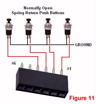
If you don’t need Toggle Switches, Figure 11 shows you how to wire Four Normally Open Spring Return switches to the 2097. The Buttons are soldered to the same terminals as the Toggle Switches and placed on the same 6 pin Male Header. The Common Ground connection for both the Toggle Switch and Push Button setup is made to the 2097 board at “GND”.
ADDING A TRIM WHEEL
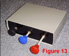
With all the wiring and assembling complete, your New Throttle Quadrant will look like this (Figure 13).
Happy Flying! PARTS Marlin P. Jones & Assoc. Desktop Aviator http://www.mpja.com http://www.DesktopAviator.com Toggle Switches Model 1090 Slide Assembly http://www.desktopaviator.com/Products/Slide/index.htm Push Button Switches Model 2097 USB Adapter http://www.desktopaviator.com/Products/Model_2097/index.htm BG Micro Toggle Switches Push Button Switches
|

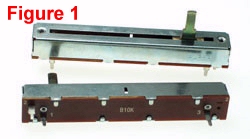 that "slides" across a strip of
carbon located within the body of the device,
that "slides" across a strip of
carbon located within the body of the device,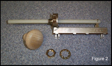
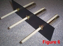 The easiest medium to shape and
drill is plastic. It does not require any specialized cutting or drilling equipment. Figure 6 shows how three Slide Assemblies are mounted to a 1/8 inch thick plastic panel (also
available from Desktop Aviator). Just measure and drill three 1/4 inch holes into the
panel and mount the Assemblies using the lock
washer and nut.
The easiest medium to shape and
drill is plastic. It does not require any specialized cutting or drilling equipment. Figure 6 shows how three Slide Assemblies are mounted to a 1/8 inch thick plastic panel (also
available from Desktop Aviator). Just measure and drill three 1/4 inch holes into the
panel and mount the Assemblies using the lock
washer and nut.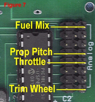 Figure 7 is a partial photo of the
2097. It shows the Eight available Analog Inputs;
of which we will be using 3 at this time. Take the
3 pin connector from the Fuel Mixture slide
assembly (RED Knob) and plug it into the #1 position on the 2097 board. Now take the Prop
Pitch (Blue Knob – If Used) and connect it to the
#4 position on the 2097. And finally, take the 3
pin connector from the Throttle (Black Knob) and
connect it to the #5 position on the 2097. That’s it!
Figure 7 is a partial photo of the
2097. It shows the Eight available Analog Inputs;
of which we will be using 3 at this time. Take the
3 pin connector from the Fuel Mixture slide
assembly (RED Knob) and plug it into the #1 position on the 2097 board. Now take the Prop
Pitch (Blue Knob – If Used) and connect it to the
#4 position on the 2097. And finally, take the 3
pin connector from the Throttle (Black Knob) and
connect it to the #5 position on the 2097. That’s it!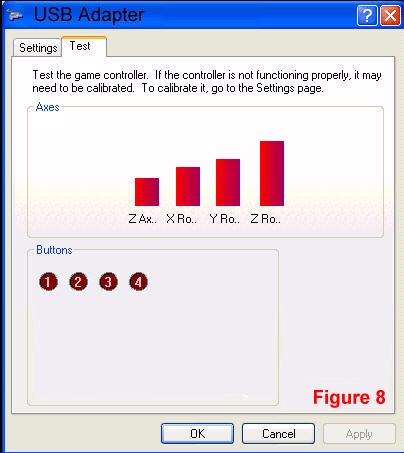
 We still have 5 available analog
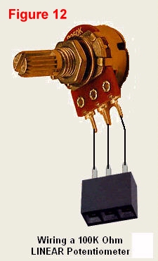
Inputs, so why now add a Trim Wheel? It’s really easy. Figure 12 shows you how to wire a Rotary Type Potentiometer (100,000 ohm) to the 3 pin connector. All you need to do is to mount some sort of
plastic wheel to the shaft of the potentiometer and make these 3 easy wiring connections (you
might consider using a shielded RCA Cable).
Then plug the connector into the 2097s Analog
Input at position #8; then calibrate and assign
the pot as your new Trim Wheel. For a more
realistic Trim Wheel, you might consider using a
Multi-Turn Potentiometer in place of the single turn pot as shown.
We still have 5 available analog
Inputs, so why now add a Trim Wheel? It’s really easy. Figure 12 shows you how to wire a Rotary Type Potentiometer (100,000 ohm) to the 3 pin connector. All you need to do is to mount some sort of
plastic wheel to the shaft of the potentiometer and make these 3 easy wiring connections (you
might consider using a shielded RCA Cable).
Then plug the connector into the 2097s Analog
Input at position #8; then calibrate and assign
the pot as your new Trim Wheel. For a more
realistic Trim Wheel, you might consider using a
Multi-Turn Potentiometer in place of the single turn pot as shown.