If you've been reading my articles
found in FlightSim.com, you might have noticed that 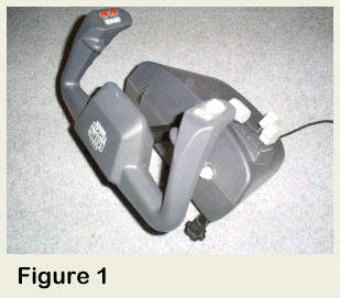 I'm a stickler for Realism.
Realism
in the flight Simulator software I use and the Hardware I connect to it.
So deciding which Flight Yoke to add to my cockpit was a no-brainer. CH
Products! The FSY21U (Fig. 1) was my first and only choice. Beautifully
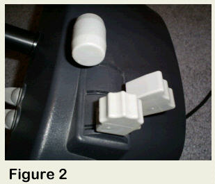
built, easy of calibration and a thrill to use. BUT! CH Products did
miss the point by using 3 small lever controls in their design (Fig 2).
I programmed these levers to control Engine RPM (Throttle), Fuel Mix and
finally Elevator Trim Control. While this scheme did work but it
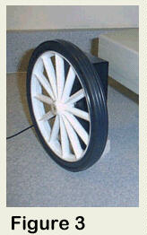
did become a "drag" after a while. So in-stepped Desktop Aviator. They designed a Throttle Quadrant with Cessna Style
push-pull levers, a Parking Brake and an Elevator Trim Wheel (Fig 3).
The Elevator Wheel has a 7.5in diameter plastic wheel mounted to a 100K
ohm potentiometer (Model #1065). When I saw this, my own wheels began to
turn. What if, I can easily modify a CH Flight Yoke to accept Desktop Aviator's Trim Wheel? Well, I tried
it, and the end result was Fantastic!
 In the next few paragraphs, I will show
you how you can just plug the Trim Wheel into the Yoke to Easily and
Effortlessly control the Pitch Attitude of your aircraft by just turning
the 7 inch plastic wheel. Rotate the Trim Wheel down for Nose Up and
Rotating the Wheel Up for Nose Down attitude. What count be easier?
In the next few paragraphs, I will show
you how you can just plug the Trim Wheel into the Yoke to Easily and
Effortlessly control the Pitch Attitude of your aircraft by just turning
the 7 inch plastic wheel. Rotate the Trim Wheel down for Nose Up and
Rotating the Wheel Up for Nose Down attitude. What count be easier?
Don't want to use the Trim Wheel
anymore tonight? Just unplug it; The CH Yoke's levers will automatically
be connected for normal operation. So now is a good place
for the disclaimer. I do not accept any
responsibility for the mis-wiring or any damage any mis-wire might
cause. Or any damage or Voided Warranty made to your Computer and/or CH
Products Flight Yoke. But if you follow these
instructions and have some knowledge of soldering techniques and
electronics, there should be no
problem.
Opening the Flight Yoke

Lets first start by turning your Flight
Yoke over and take note of the Warranty Sticker (Fig 4).
"Warranty VOID is Seal is Broken". Strong
Words from the manufacturer. If your Yoke is New, I do not ecommend
breaking the seal. But if the Yoke is older then the manufacturers
warranty (see the instruction manual that came with your purchase to
determine the length of the warranty), Break the Seal! And begin to
remove the 8 Phillips screws located around the perimeter of the base
(Note: There are 6 screws that can be easily located. There is another 2
screws being covered by the rubber feet located in the corners of the
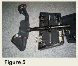
base. With a screwdriver, pry the feet up to expose the 2 screws). With
the Screws removed, the base easily comes apart (Fig 5). But be careful.
A number of wires (the Wire Harness) connecting the 3 Levers to the USB
Adapter are also present.
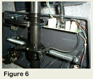
In Fig 6, notice the small circuit board in the upper right hand
corner of the lower base shell. This is the USB Adapter. It contains the
programmed HID (Human Interface Device) chip and associated circuitry.
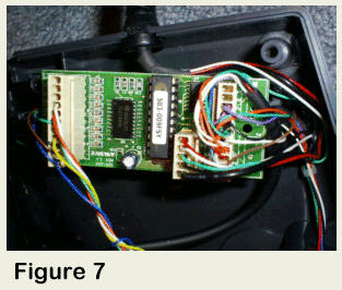
You can easily remove this circuit board just by lifting it from its
plastic mounting rails. Fig 7 shows what the USB Adapter looks like. It
is here that we will do a few minor wiring changes. But what type of
changes? I'll show you.
Retrofit Wiring Changes
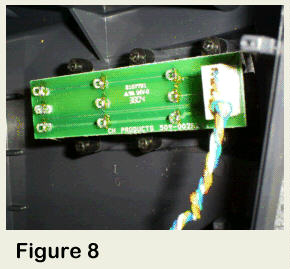
Figure 8 shows the small circuit board
where the 3 Yoke Levers are soldered. To make things simpler, we'll
modify the lever located closest to the outside of the Yoke (I
programmed the same lever as a Trim Wheel). The 3 levers are made up of
100k ohm potentiometers wired in parallel. The Wiper arms (the terminal
located in the center of the three soldering points on the "pot") are
brought to three different points of the USB Adapter by the wire
harness. So what if we parallel solder the same three terminals of the
Desktop Aviator's Trim Wheel to these points? We will have a Realistic
Elevator Trim Wheel.
What We Plan to Do
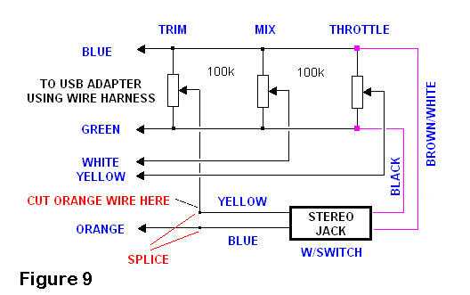
Figure 9 shows a schematic on what we plan
to do with this modification. Through the Stereo Jack, we will connect
the Desktop Aviator's Trim Wheel to the BLUE and GREEN wires inside the
wire harness (in parallel). The ORANGE wire, also from the wire harness,
will be cut and the Stereo Jack will be connected is SERIES with this
wire. That's all there is to it. Desktop Aviator will provide the Stereo
Jack pre-wired using these colors. All you need to do is to follow the
color-code as per the schematic.
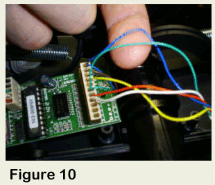
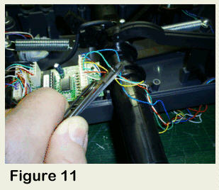
As seen in Figure 10, locate the BLUE and
GREEN wires inside the wire harness closest to the USB Adapter.
Carefully strip back the insulation to expose the bare wire (see Fig
11).
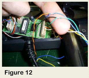
Take the BROWN/WHITE wire from the Stereo
Jack and splice it with the BLUE wire from the USB Adapter. Then solder.
Next, take the BLACK wire from Stereo Jack and splice the GREEN wire
from the USB Adapter (see Fig. 12). Then, using electrical tape, cover
the exposed wires, making sure that they are not "Shorted".
Finally, locate the ORANGE wire inside the
wire harness and cut it about 2 inches from the USB Adapters' Molex
Connector. Take the ORANGE wire closest to the Molex Connector, splice
the BLUE wire (from Jack). Take the other side of the ORANGE wire and
splice it to the YELLOW wire from the Stereo Jack. Solder both
connections and cover with electrical tape. The Retrofit is now
complete.
Mounting the Stereo Jack
The Stereo Jack supplied with the Retrofit
kit is a relatively small part. The thickness of the plastic base of the
Flight Yoke will not allow the Jack to be mounted unless modified
slightly.
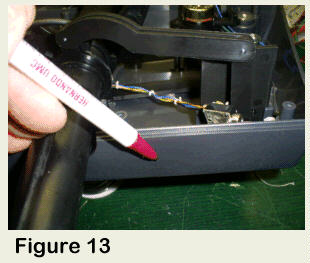
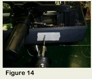
Locate an area on the bottom base section of the Yoke
where the mounting of the Jack will not interfere with the movements on
the mechanism. A good location is illustrated in Fig. 13. With the area
located, place masking take to protect the Yoke's finish and drill a
1/8in pilot hole (Fig 14). With the pilot hole drilled, change your
drill bit to a .237in (1.4in will also work) and drill the second hole
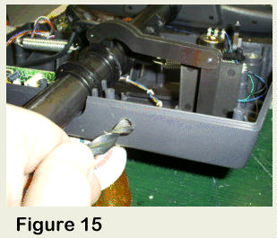
inside the first. Now the tricky part. Take a 3/8in drill bit. And BY
HAND, rotate the bit inside the 1/4in hole just drilled. Figure 15
illustrates this. Twist the drill bit until enough plastic is removed so
that the mounting nut from the Stereo Jack can easily fit inside. When
enlarged to the proper diameter, carefully insert the Jack into the hole
and screw it to the base using the supplied nut. Do not over tighten.
Re-assembly the Flight Yoke.
Above is a simplified
Schematic. It tells the WHOLE Story on what we want to do to Mofify the
Flight Yoke. Remember the Stereo Jack is a pre-wired item that comes
with your purchase of the Trim Wheel Retrofit Kit.
Calibrating the Trim Wheel
If your CH Flight Yoke was calibrated
correctly prior to add the Trim Wheel, no other calibration is required.
The Trim Wheel and the Lever on the Yoke are both 100K ohm
potentiometers, so no additional calibrating is needed.
Using the Trim
Wheel
With your Flight Simulator software
running, select your favorite aircraft. Plug in the Trim Wheel into the
Stereo Jack and rotate it Up and Down. You will note significant Nose Up
and Down attitude. Use your Trim Wheel to adjust for level flight at
cruising altitude. If you find that rotating the Trim Wheel UP, the nose
of your aircraft goes DOWN, just go into you FS's Assignment Window and
click on REVERSE operation for the Elevator Trim. If you wish to revert
back to your normal Flight Yoke Levers, just remove the Trim Wheel from
the Stereo Jack. The Yoke's internal lever will automatically be
reconnected.
Mounting the Trim Wheel
In the Real World, Elevator Trim Wheels
are located just beneath the Throttle Quadrant and to the right of the
Flight Yoke. Your New Trim Wheel can be mounted to your flight deck
using aluminum "L" Brackets. Or better yet, a strip of Velcro , if you
wish the Wheel to be removed easily.
If you have any
comments or just wish to say "Hi", you can reach me at "Support@DesktopAviator.com"
Elevator Trim
Wheel
Retrofit Kit
for CH Products Flight
Yoke
You Get the Elevator
Trim Wheel and Pre-wired Stereo Jack
at:
http://www.desktopaviator.com/Products/Retrofit_Trim/index.htm
Attention INTERNATIONAL Buyers . .
.
If you live outside the U.S., and Canada & wish to
purchase this item; Please email us your complete address. I will be
more that happy to email you the required shipping Fees for USPS Air
Mail.
Any Over Payments are Quickly REFUNDED via
Paypal.
Please Click HERE for TERM & CONDITIONS
on International
Sales & Shipping.

Please eMail me
at:
Support@DesktopAviator.com