|
|
|
INSTALLATION INSTRUCTIONS for the Model 1030 & 1040 THROTTLE QUADRANTS |
| ||
|
|
|
|
Below are the Instructions to install the CESSNA THROTTLE QUADRANT (MODEL #s 1030 - SKYHAWK VERSION & 1040 - SKYLANE VERSION) | ||
|
|
|
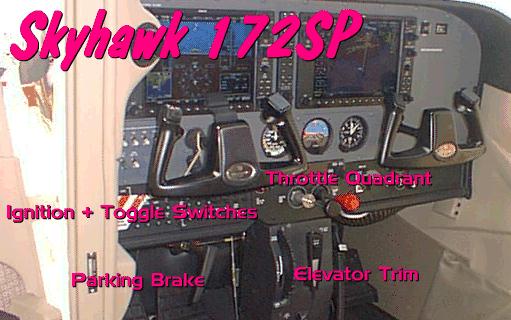
Thank you for your purchase of our NEWEST! Cessna Avionics Panel - The PUSH-PULL THROTTLE Quadrant. At the present time, we have two Models; the 1030 and the 1040. The Model 1030 depicts the Throttle Layout of a Cessna Skyhawk 172SP. This consists of a THROTTLE (Black Knob)- Mixture (Red Knob) and Flaps Adjust Spring Return Toggle Switch. The Model #1040 depicts the Throttle Layout of the Cessna Skylane. This panel consists of a THROTTLE (Black Knob) - Propeller Pitch Adjust (Blue Knob) and the Fuel Mixture Adjust (Red Knob). When correctly calibrated and programmed within the Flight Simulator "ASSIGN" window, you will have the time of your life simulating flights around the world! The addition of Push-Pull Throttle Controls to your Desktop Aviation setup, will, without a doubt, give you a Hightened THRILL of Actually Flying your Favorite Airplane.
Below, you will find the detailed instructions for Calibration and Programming of your New Throttle Quadrant. Calibration of the Throttle Quadrant is essential for the proper operation and added realism of flying YOUR Cessna. So read these instructions carefully and you will have Years of Exciting Flight Simulations.
Model #1030 - Skyhawk Contains THROTTLE - Fuel Mixture - Flaps Adjust
Model #1040 - Skylane Contains THROTTLE - Prop Pitch Adjust - Fuel Mixture
INSTALLING THE ELEVATOR TRIM WHEEL
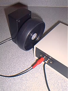
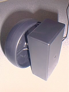
If you have purchased the Optional Trim Wheel, you can now attach it to the Throttle Panel as seen in the photo to the right. A 2 foot long cable can be found protruding from the back of the Trim Wheel. This cable is terminated to an RCA Plug. While looking at the back of the Throttle Panel, notice the two RCA Jacks; one RED & the other is WHITE. Take the RCA Plug from the Elevator Trim Wheel and insert it into the RED Jack (the left most of the 2 jacks). The second RCA Jack is internally connected to the USB Adapter. If you wish, you can connect a toggle or push button switch to this jack and then program its function into your MS Flight Simulator.
NOTE: THE PLASTIC WHEEL CAN NOT BE REMOVED FROM THE CONTROL SHAFT. TRYING TO REMOVE THE WHEEL WILL DAMAGE THE DEVICE!
Also note: The Control for the Elevator Trim Wheel will rotate approx. 350 degrees (similar to a volume control on a radio). Trying to rotate the Wheel beyond this point WILL DAMAGE the Device. It is also recommended that the Trim Wheel be attached to your Flightdeck via Velcro, Glue or Aluminum Brackets.
This jack is intended for our NEW! Parking Brake that will be available in the near future.
Calibrating the CESSNA THROTTLE Quadrant Just follow the easy instructions located below each photograph.
With your XP Computer running; Click on the 'START' Icon; 'Control Panel', then...
... "Game Controllers"
With your Throttle Quadrant connected to the USB Port, your Computer will sense the Throttle as
"USB
Adapter".
Click on 'Properties'.
After pressing "Properities", you will see the window illustrated above. You will then Calibrate your Throttle Quadrant as follows:
X Axis - Throttle (Black
Knob) Y Axis - Mixture (Red Knob)
SLIDE will be used for the Prop Pitch (Blue Knob - Model 1040 ONLY)
Z Axis - Optional Elevator Trim Wheel (Option for BOTH Models) Optional Trim Wheel seen at Right -->
Buttons #1 and #2 - Spring Toggle Switch (Model #1030 ONLY) for Flaps or Gear Flaps/Gear DOWN = RED Button #1 Flaps/Gear UP = RED Button #2
RED Button #3 Unused, but wired for future Parking Brake
Hat Switch - NOT USED
TESTING THE FLAPS SWITCH (MODEL 1030 ONLY)
If you purchased the model 1030 Skyhawk Throttle Quadarant you will find a Spring Return Toggle Switch to the right on the front panel. Press the Toggle Switch DOWN, the Flaps go DOWN. If you flip the Toggle Switch UP, the Flaps go UP. So now is a good time to TEST the Flaps. With the "USB Adapter" Properties window on-screen; press the Flaps switch DOWN. NOTE that the #1 RED Circle Lights. When you release the Toggle Switch, the built-in spring returns the handle to its Center position. Now, flip the switch UP. Now Notice that the #2 RED Circle Lights. This Toggle Switch can also be programmed to Extend or Retract the Landing Gears. Now proceed to the next step.
Flipping the Toggle Switch DOWN - the #1 RED Circle LIGHTS
Flipping the Toggle Switch UP - the #2 RED Circle LIGHTS
CALIBRATING THE THROTTLE CONTROLS
At the TOP of the "Properities" window; Click "Settings"
With the "Settings" Window showing; Click "Calibrate"
The Calibration Wizard will then be Displayed. Click on the "Next" Icon
With the above window showing, it asks you to "Leave the handle centered, then press Enter". For our Throttle calibration, pull the Throttle Handle (Black) and the Mixture Handle (Red) OUT about 1 3/4 inches from the panel face. Then press "NEXT"
You will now be greeted with this window. Here you will calibrate the Throttle and Mix controls (X & Y Axis). Pull the BLACK knob OUT; push the Red Knob IN. the "+" should be in the upper Right hand corner of the calibration box. Now, Pull the Red Knob OUT - "+" Icon now in the lower Right hand corner. Push the Black Knob IN - "+" on will now be in the Lower Left hand corner. Now Push the Red Knob IN - "+" Icon is now at the Upper Left hand corner. REPEAT this procedure another 3 or 4 times. Your computer is now "Learning" about your Throttle Control. Ultimately, what we want is when BOTH Throttle and Mix controls are PULLED OUT FULLY, the "+" Icon is to be in the UPPER LEFT HAND Corner of the calibration box. When you have completed this process; Click on "Next".
You will again be asked to Center the Handle, but for our Throttle Quadrant, place the Black and Red Knobs about 1 3/4 inches from the panel's faceplate. Then Click "NEXT" The Next Section is to Calibrate the Prop Pitch Control (Model 1040). If you purchased the Model 1030, SKIP THIS PROCEDURE by Clicking on "Next".
This section allows you to calibrate the Prop Pitch Control (Blue Knob). With this window displayed, pull the Blue Knob IN then OUT. You will see the Blue bar in the window move from Left to Right. Do this 3 or 4 times. Then Click "NEXT" CALIBRATING THE OPTIONAL TRIM WHEEL If you have purchased the Optional Trim Wheel, it is now time to calibrate it. With the Trim Wheel connected to the Throttle Panel as discussed earlier; spin the wheel its full rotation. The Z Axis bar should move from left to right and back again with the rovolution of the Wheel. If the Blue Bar does not move, click on "Display raw data", as seen below. Spin the Trim Wheel again. Now you will see the digital data as the wheel is turned (see white arrow). Repeat the spinning of the Trim Wheel about 3 times; then click on "Next". This now completes the Calibration of your THROTTLE Panel. But we're not finished yet. We still need to program the Throttle Functions into our MS Flight Simulator. For this procedure, I will use the MS Flight Simulator 2002. If you have FS2004, that's no problem. The programming is still the same, MS might have just changed the terminalogy a bit. Programming Your Flight Simulator As previously encountered above, a picture is worth a thousand words. I will use photos extensively throughout the programming procedure. First; connect the THROTTLE's USB Connector to an unused USB Port. Seeing that the Throttle Panel has a 6 inch USB Cable, you might want to install the optional USB Cable Extender. When installed; load and RUN your version of MS Flight Simulator.
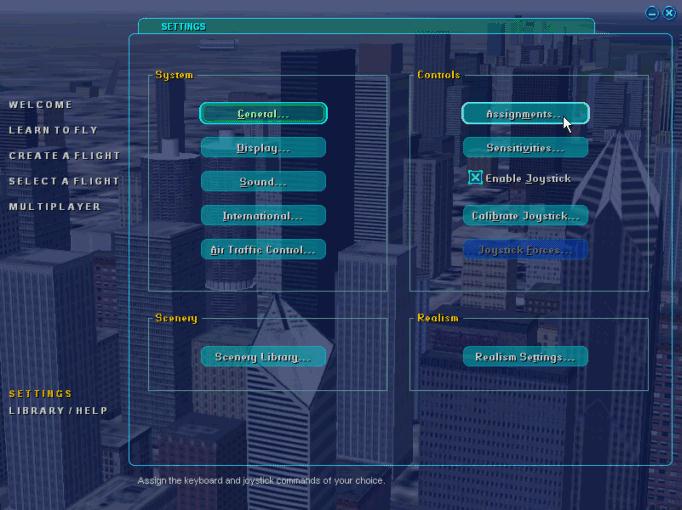
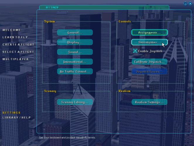
When Flight Simulator is RUNNING, Click on "SETTINGS" then "Assignments"
With the NEW Window showing; Find "Joystick Type" then "USB ADAPTER"; CLICK. Before programming any functions, scroll down the Assignment List and DELETE ANY Default asignments that your Flight Simulator might have made. Only when the Assignment List is CLEAR of any settings, you can program the Flaps Switch. If you purchased the Model 1040, the next section can be ignored.
Programming the Flaps Switch (Model 1030)
Lets first Program the Flaps Control Toggle Switch (Model #1030 ONLY) In the Assignment List, scroll down until you find "Extend flaps ...." Click
In the lower left hand side of the screen; locate and CLICK ON "Change Assignments"
With this smaller window appearing, Press the spring Return TOGGLE Switch "DOWN". The text "Button 01" will appear (see Arrow). Then CLICK "OK"
Next, find in the Assignment List "Retract flaps"; then CLICK
In the lower left hand side of the screen; locate and CLICK ON "Change Assignments"
With this smaller window appearing, Press the spring Return TOGGLE Switch "UP". The text "Button 02" will appear (see Arrow). Then CLICK "OK"
And this is how your computer should look when BOTH Flap Control Settings are Programmed. Notice that the REPEAT Bar is FULLY to the LEFT.
Programming the Throttle, Mix and Prop Pitch
To program the Throttle Controls, lets go back to the SETTINGS Window. Again, Click on "Assignments"
This time Click on "Joystick Axes"
Locate and Highloght on "Engine 1 Throttle axis"
Then Click on "Change Assignments"
With the above window showing; Pull on the Throttle Lever (BLACK). X Axis will appear in the once black smaller window (see white arrow). Then Click OK.
Back to the Assignment List; find and Highlight "Engine 1 Mixture Axis". Then Click on "Change Assignments"
With this window showing, pull the Fuel Mix Lever (RED). y Axis will appear in the once empty window. Then Click "OK"
Programming the Optional Elevator Trim If you did not purchase the Elevator Trim Wheel, skip this section.
With the Assignment Window showing again, Click and Highlight "Elevator Trim Axis". Then Click "Change Assignments"
With the above window showing, rotate the Wheel of the Optional Elevator Trim. "Z Rotation" will appear in the once blank window. Click "OK"
Programming the Prop Pitch (Model 1040 ONLY)
If you purchased the Model 1040 Throttle Panel, you have the added feature of adjusting the Pitch of the Propeller. To program this feature, Click on "Engine 1 Propeller axis" then Click "Change Assignment"
With the above window showing, Pull the BLUE Lever Out. "Slider" will appear in the once blank window. Click "OK"
Notice the Column named "Reverse". ALL Axis' MUST be Programmed for reverse operation. To do this, just click on the line to Highlight it. Then bring your computer mouse over the small "blue box"; then click. If you have FS2002, an "X" will appear. If you have FS2004 a "check mark" will be displayed. Do this for the remailing Axis', "Z Rotation" and "Slider".
If you purchased the Model 1040 and the Trim Wheel, your Assignment window should look like this (see above). Now, all you need to do is Program the Sensitivity.
Programming the Sensitivity of the Panel
Back to the now famous "Settings Window", Click on "Sensitivities"
Then find and Click on under Joystick Type, "USB ADAPTER"
Click on "Simple". Notice the 2 Blue Bars. The left most saying "All axes". The right saying "All null zones". Take note of the placement of both bars. "All axes" MUST be all the way to the RIGHT, while the "All null zones" is places all the way to the LEFT. THIS IS IMPORTANT. If these Bars are not set correctly, the Flight Simulator will NOT provide FULL Lever deflection. Example; When you push the Throttle All the way IN, your engine Tach will read only 1800RPM, not the full RPM needed for Takeoff. When Axis setting is complete; Click "OK" This completes the Calibration and Programming of the Throttle Panel
|
| ||
|
|
|
|
| ||