|
|
|
INSTALLATION INSTRUCTIONS for the Model 1030HiR & 1040HiR THROTTLE QUADRANTS With High Resolution USB Adapter NOW Available - Our New "B" Series |
| ||
|
|
|
|
Below are the Instructions to install the CESSNA THROTTLE QUADRANT (MODEL #s 1030HiR - SKYHAWK VERSION & 1040HiR - SKYLANE VERSION) | ||
|
|
|
Thank you for your purchase of our NEWEST! Avionics Panel - The PUSH-PULL THROTTLE Quadrant. At the present time, we have two Models; the 1030HiR and the 1040HiR. The Model 1030 depicts the Throttle Layout of a Cessna Skyhawk 172SP. This consists of a THROTTLE (Black Knob)- Mixture (Red Knob) and Flaps Adjust Spring Return Toggle Switch. The Model #1040HiR depicts the Throttle Layout of the Cessna Skylane. This panel consists of a THROTTLE (Black Knob) - Propeller Pitch Adjust (Blue Knob) and the Fuel Mixture Adjust (Red Knob). When correctly calibrated and programmed within the Flight Simulator "ASSIGN" window, you will have the time of your life simulating flights around the world! The addition of Push-Pull Throttle Controls to your Desktop Aviation setup, will, without a doubt, give you a Hightened THRILL of Actually Flying your Favorite Airplane.
By incorporating a 10 Bit Resolution USB Adapter Module, the 1030HiR and 1040HiR will give you MORE precise control over your aircraft as well as allowing for the Optional Elevator Trim Wheel (Model 1050 or 1060)
Below, you will find the detailed instructions for Calibration and Programming of your New Throttle Quadrant. Calibration of the Throttle Quadrant is essential for the proper operation and added realism of flying YOUR Cessna. So read these instructions carefully and you will have Years of Exciting Flight Simulations.
Model #1030HiR & 1030HiRES - B / Skyhawk Contains THROTTLE - Fuel Mixture - Flaps Adjust
And 2 RCA Jacks for additional switches
Model #1040HiR & 1040HiRES - B / Skylane Contains THROTTLE - Prop Pitch Adjust - Fuel Mixture
You can easily add our Elevator Trim Wheel and Parking Brake to either Quadrants
We are now able to deliver our 1030HiRES and 1040HiRES Throttle Quadrant with our own USB Adapter. How do you know if you have the Series "B" Quadrant? Just turn the Throttle Quadrant over and locate the label on the bottom. If the Model number contains the letter "B"; you have our Newest Throttle (Ex 10930HiRES - B). Programming the Series "B" Throttle is the same as our standard model. The differences will be apparant then you Calibrate the Throttle using the "Game Controllers" window located inside the "Control Panel".
The Most Obvious change is when you plug the Series "B" Throttle into yout computer's USB Port, your computer will sense the Throttle and automatically load the needed driver software. You will notice a small white window appear on the computer screen. It will indicate that New Hardware was found; "DTA Throttle Quadrant".
So proceed with the Calibration and Installation information below; I will highlight the programming differences with the Series "B" Throttle Quadrant.
Connecting the Throttle to your Computer Connecting your New Throttle Quadrant to your computer is a simple thing. All you need to do is to insert the Throttle's USB Plug into an unused USB receptical on the front or back of your computer. Even if you have multiple USB connections, your computer will sense the Throttle and load the proper software for its operation.
If you purchased the Optional Elevator Trim Wheel, locate the "Stereo Jack" on the back of the Quadrant and insert the plug protuding from the Trim Wheel (See Above). The WHITE RCA plug is used to install the Optional Parking Brake. If you purchase one, insert it Here. The RED RCA plug can be used to install the Optional Carb Heat Switch, or if you wish, you can install a Normally Open Switch of your choice Here.
Calibrating the THROTTLE Quadrant Just follow the easy instructions located below each photograph.
With your XP Computer running; Click on the 'START' Icon; 'Control Panel', then...
... "Game Controllers"
With your Throttle Quadrant connected to the USB Port, your Computer will sense the Throttle as
"USB
Adapter".
Click on 'Properties'.
If you have the Series "B" Throttle, the computer will
display "DTA Throttle
Quadrant"
After pressing "Properities", you will see the window illustrated above. You will then Calibrate your Throttle Quadrant as follows: For Series "B" Throttles, see Below"
Z Axis will be used for the THROTTLE Control (Black Knob) X Rotation will be used for the Fuel Mixture (Red Knob) Y Rotation will be used for the Prop Pitch (Blue Knob - Model 1040HiRED Only) Z Rotation will be used for the Optional Elevator Trim Wheel (Model # 1050 or 1060)
RED Buttons #1 and #2 - Spring Toggle Switch (Model #1030HiR ONLY) for Flaps or Gear Flaps/Gear UP = RED Button #2 Flaps/Gear DOWN = RED Button #1
RED Button #3 Wired for Parking Brake (Model #1070/2002 or 1070/2004) (White RCA Receptical on BACK) RED Button #4 Wired for Optional Caborator Heat Switch (Model #1080) (RED RCA Receptical on BACK)
Hat Switch - NOT USED
TESTING THE FLAPS SWITCH (MODEL 1030HiR & 1030HiRES - B ONLY)
If you purchased the Model 1030HiR Skyhawk Throttle Quadarant you will find a Spring Return Toggle Switch to the right on the front panel. Press the Toggle Switch DOWN, the Flaps go DOWN. If you flip the Toggle Switch UP, the Flaps go UP. So now is a good time to TEST the Flaps. With the "USB Adapter" Properties window on-screen; press the Flaps switch DOWN. NOTE that the #1 RED Circle Lights. When you release the Toggle Switch, the built-in spring returns the handle to its Center position. Now, flip the switch UP. Now Notice that the #2 RED Circle Lights. This Toggle Switch can also be programmed to Extend or Retract the Landing Gears. Now proceed to the next step.
Flipping the Toggle Switch DOWN - the #1 RED Circle LIGHTS
Flipping the Toggle Switch UP - the #2 RED Circle LIGHTS
CALIBRATING THE THROTTLE CONTROLS
At the TOP of the "Properities" window; Click "Settings"
With the "Settings" Window showing; Click "Calibrate"
The Calibration Wizard will then be Displayed. Click on the "Next" Icon
With the above window showing, it asks you to "Leave the handle centered", just click on the "NEXT" icon.
This section allows you to calibrate the Throttle Control (Black Knob). With this window displayed, pull the Black Knob IN then OUT. You will see the Blue bar in the window move from Left to Right. Do this 3 or 4 times. Then Click "NEXT"
This section allows you to calibrate the Fuel Mixture Control (Red Knob). With this window displayed, pull the Red Knob IN then OUT. You will see the Blue bar in the window move from Left to Right. Do this 3 or 4 times. Then Click "NEXT" The Next Section is to Calibrate the Prop Pitch Control (Model 1040HiR & 1040HiRES B). If you purchased the Model 1030HiR, this Window Will not appear.
This section allows you to calibrate the Prop Pitch Control (Blue Knob). With this window displayed, pull the Blue Knob IN then OUT. You will see the Blue bar in the window move from Left to Right. Do this 3 or 4 times. Then Click "NEXT" The Next Section is to Calibrate the Optional Elevator Trim Wheel (Model 1050/1060). The Trim Wheel WILL NOW Operate on BOTH the Model 1030HiR and the 1040HiR Quadrants. If you do not have the Trim Wheel, SKIP THIS PROCEDURE by Clicking on "Next".
This section allows you to calibrate the Optional Elevator Trim Wheel. With this window displayed, turn the Trim Wheel Fully in BOTH Directions. You will see the Blue bar in the window move from Left to Right. Do this 3 or 4 times. Then Click "NEXT"
This now completes the Calibration of your THROTTLE Panel. But we're not finished yet. We still need to program the Throttle Functions into our MS Flight Simulator. For this procedure, I will use the MS Flight Simulator 2004. If you have FS2002, that's no problem. The programming is still the same, MS might have just changed the terminalogy a bit. Calibrating the Series "B" Throttle Quadrant As indicated above, you need to Calibrate the Control Slides inside your Throttle. This is also true if you have our Series "B" Panel. To proceed, plug the Series "B" Throttle into an unused USB Port. Your computer will sense and load the needed hardware to make the Throttle operate. As shown above, click on the "START" icon; then "Game Controllers". The following window will
open.
Notice that the Series "B" Panel shows the X/Y Axis, Z Axis, X Rotation, Y Rotation, Z Rotation, Slide, Dial and 16 Digital Switch Buttons. The X/Y Axis is not used with this application, so just click on "Next" when asked. The Z Axis is wired to the THROTTLE (Black Knob). X Rotation is used for the Fuel Mix Slide (Red Knob). The Y Rotation is used for Prop Pitch (Blue Knob). Prop Pitch is found in the Model 1040HiRES - B. If you purchased the 1030HiRES - B, just click "Next" then this Axis is displayed. The Z Rotation is used for the Elevator Trim Wheel (Model 1060 or 1060B). The Slide and Dial Axis are not used with this application, so when asked, just click "Next". Programming the Buttons is the same as discussed below. The difference is in the calibration on the slides. So lets get started. Click on the "Settings". The window seen below will open.
Seeing that the Throttle does not use the X/Y Axis; just click on "Next"
The Z Axis window is now displayed. Click on the "Display raw data" and slide the Throttle control all the way in then out about 5 or 6 times. Note that the axis display will show 0 to 1022 when you activate the Throttle Slide. When complete, click on "Next".
The X Rotation Axis window is now displayed. Click on the "Display raw data" and slide the Fuel Mix control all the way in then out about 5 or 6 times. Note that the axis display will show 0 to 1022 when you activate the Fuel Mix Slide. When complete, click on "Next".
If you purchased the Model 1030HiRES - B Throttle Quadrant, this axis is not available, just click on "Next". If you have the Model 1040HiRES - B, Please continue.
The Y Rotation Axis window is now displayed. Click on the "Display raw data" and slide the Prop Pitch control all the way in then out about 5 or 6 times. Note that the axis display will show 0 to 1022 when you activate the Prop Pitch Slide. When complete, click on "Next".
If you purchased the Optional Elevator Trim Wheel Model 1060 or 1060B, proceed with the following; if not, click "Next".
The Z Rotation Axis window is now displayed. Click on the "Display raw data" and rotate the Trim Wheel all the way Clockwise, then Counter-clockwise about 5 or 6 times. Note that the axis display will show 0 to 1022 when you rotate the Trim Wheel. When complete, click on "Next".
The Slide Axis window will now be displayed. This Axis is not used with the Throttle, so just click "NEXT"
The Dial Axis window will now be displayed. This Axis is not used with the Throttle, so just click "NEXT".
It's now time to program your Flight Simulator to accept these settings and configurations. Programming Your Flight Simulator As previously encountered above, a picture is worth a thousand words. I will use photos extensively throughout the programming procedure. First; make sure the THROTTLE's USB Connector to an unused USB Port. And that all Optional equipment is also installed. 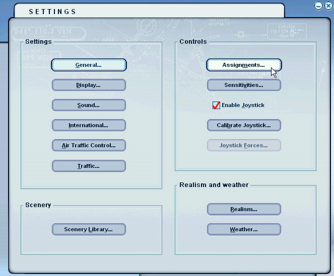
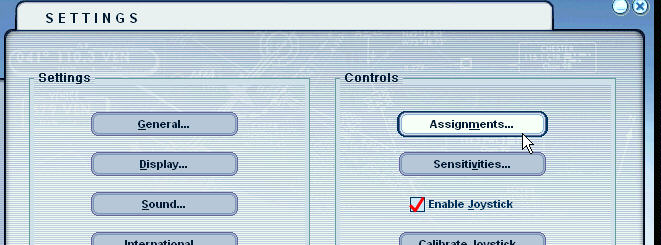
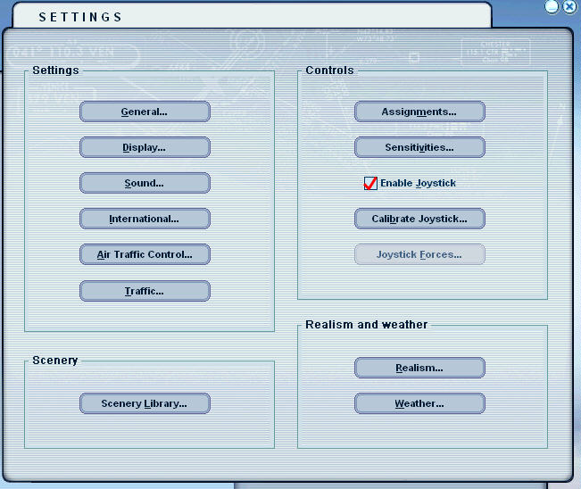
When Flight Simulator is RUNNING, Click on "SETTINGS" then "Assignments"
With the NEW Window showing; Find "Joystick Type" then "USB Adapter"; ("DTA Throttle Quadrant" for the Series "B"). This display wiCLICK. Before programming any functions, scroll down the Assignment List and DELETE ANY Default asignments that your Flight Simulator might have made. Only when the Assignment List is CLEAR of any settings, you can program the Flaps Switch. If you purchased the Model 1040, the next section can be ignored.
Programming the Flaps Switch (Model 1030HiR)
Lets first Program the Flaps Control Toggle Switch (Model #1030 ONLY) In the Assignment List, scroll down until you find "Flaps extend incrementally (for Fs2004). Extend flaps ....(for FS2002)" Click
In the lower left hand side of the screen; locate and CLICK ON "Change Assignments"
With this smaller window appearing, Press the spring Return TOGGLE Switch "DOWN". The text "Button 01" will appear (see Arrow). Then CLICK "OK"
Next, find in the Assignment List "Flaps retract incrementally" (for FS2004) or "Retract flaps" (for FS2002); then CLICK
In the lower left hand side of the screen; locate and CLICK ON "Change Assignments"
With this smaller window appearing, Press the spring Return TOGGLE Switch "UP". The text "Button 02" will appear (see Arrow). Then CLICK "OK"
And this is how your computer should look when BOTH Flap Control Settings are Programmed. Notice that the REPEAT Bar is FULLY to the LEFT.
Programming the Optional Parking Brake (Model 1070/2004)
Just as you programmed the Flaps Switch, you can easily program the Optional Parking Brake with either the Skylane or Skyhawk Throttle Quadrants. The Parking Brake comes in one Model for Both FS2002 and FS2004.
The Parking Brakes are made up of a round magnet connected to the plastic shaft of the brake. When the lever is pull all the way OUT the magnet is brought into contact with a reed switch. This switch closes due to the effects of the magnet. When programmed in the Assignment Window on the FS2002 or FS2004, the Flight Simulator will sense this closure as the setting of the Brake. When you push the lever all the way in, the magnet moves away from the reed switch thus allowing the switch to Open. The Flight Simulator senses this open circuit as the Release of the Parking Brake.
INSTALLATION of the Parking Brake (Models 1070/2004)
Take the RCA cable from the Parking Prake and push it onto the "WHITE" RCA receptical located on the back of the Throttle Quadrant. Either RCA Jack will work just fine.
Programming the Parking Brake for FS2004
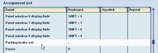
Assigning the Parking Brake within the FS2002 or FS2004 software is very easy. Before running Flight Simulator, push the Parking Brake Lever all the way IN. This will assure that the internal magnet is not in contact with the forward Reed Switch. Plug the RCA connector from the Parking Brake into the "WHITE" RCA Jack on the back of the Throttle Quadrant. You can now load and run FS2002 or FS2004 at this time. Click "Settings" and "Assign". Locate "Parking Brake Set" (see below).
Locate "Parking Brake Set" in the Assignment Window of your FS2004 and Highlight with a mouse click.
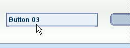
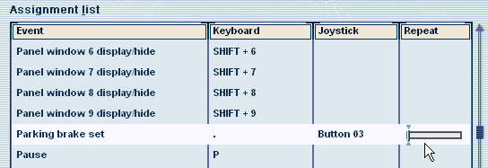
Then 'click' on "Change Assignment" and pull the Parking Brake Level all the way OUT. You will now see that Button 03 has been programmed for the Parking Brake.
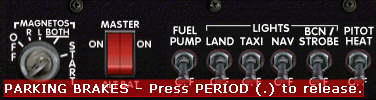
Your Assignment List for FS2004 should Look like this. Then when running Flight Simulator 2004, pull the Parking Brake OUT (Brake SET) before loading an Aircraft Type. For example, say you loaded the Cesna Skyhawk; in the lower left hand corner, you will see the wording: "PARKING BRAKE - Press PERIOD (.) to release.
To release the Brake, push the Parking Brake all the way IN. The "Parking Brake" label will disappear. It's now time to apply Full power and take to the skies.
Programming the Parking Brake is now COMPLETE
Optional Carburetor Heat Switch On the back of the Throttle Quardant, you proberly noticed a second RCA Receptical (RED). This is BUTTON 04 and it can be connected to another switch if you like. How about using this Extra RCA Receptical for Carb Heat? Our Carborator Heat Switch Model 1080 is similiar in appearance to the Parking Brake but with a 1 inch Diameter Round Head instead of the "T" Handle. If you wish to purchase the Carb Heat Switch, just email me at:
Programming the Throttle, Mix and Prop Pitch
To program the Throttle Controls, lets go back to the SETTINGS Window. Again, Click on "Assignments"
This time Click on "Joystick Axes" For the Series "B" - "DTA Throttle Quardant"
Locate and Highlight on "Engine 1 Throttle axis"
Then Click on "Change Assignments"
Then Click OK.
Back to the Assignment List; find and Highlight "Engine 1 Mixture Axis". Then Click on "Change Assignments"
With this window showing, pull the Fuel Mix Lever (RED). Y Axis will appear in the once empty window. Then Click "OK"
Programming the Prop Pitch (Model 1040HiR & 1040HiRES - B ONLY)
If you purchased the Model 1040HiR Throttle Panel, you have the added feature of adjusting the Pitch of the Propeller. To program this feature, Click on "Engine 1 Propeller axis" then Click "Change Assignment"
With the above window showing, Pull the BLUE Lever Out. "Slider" will appear for FS2002 "Z Axis" for FS2004, in the once blank window. Click "OK"
Programming the Optional Elevator Trim Wheel
If you purchased the Optional Elevator Trim Wheel, now is the time to program its operation into your FS2002 or FS2004 Flight Simulator. Below is the Assignment Window of the FS2004. To program the Trim Wheel, just highlight "Elevator Trim Axis"; then click "Change Assignment". As seen above, a secondary window will appear. To assign the trim wheel just move the wheel either UP or DOWN. The text "X Rotation" will appear. Click OK.
Above is a photo on the Assignment Window from FS2004 Flight Simulator. All elements of the Model 1040HiR Throttle Quadrant are programmed and showing in this window. Your FS Window should look the same. If not, just Re-Program the needed function. Now, notice the Column named "Reverse". EXCEPT for Elevator Trim all other Axis' MUST be Programmed for reverse operation. To program for Reverse Operation, just click on the line to Highlight it. Then bring your computer mouse over the small "blue box"; then click. If you have FS2002, an "X" will appear. If you have FS2004 a "check mark" will be displayed.
Programming the Sensitivity of the Panel
Back to the now famous "Settings Window", Click on "Sensitivities"
Then find and Click on under Joystick Type, "DTA Throttle Quadrant"
Click on "Simple". Notice the 2 Blue Bars. The left most saying "All axes". The right saying "All null zones". Take note of the placement of both bars. "All axes" MUST be all the way to the RIGHT, while the "All null zones" is places all the way to the LEFT. THIS IS IMPORTANT. If these Bars are not set correctly, the Flight Simulator will NOT provide FULL Lever deflection. Example; When you push the Throttle All the way IN, your engine Tach will read only 1800RPM, not the full RPM needed for Takeoff. When Axis setting is complete; Click "OK" This completes the Calibration and Programming of the Throttle Panel
|
| ||
|
|
|
|
| ||