

|
Wiring Your Model 2310 and 2312 Helicopter Simulator Controller |

|
Thank you for your purchase of our NEW Hilo Flight Sim Controller Board. The board comes in two versions; the 10-Bit Resolution and the 12-Bit Resolution. The installation as well as the wiring for both are the same so references to a specific Model will not be made. Please note that both the 2310 and the 2312 boards accept 5 Analog inputs. For the proper operation of both boards, ALL FIVE Analog Inputs MUST be conected to either a 100K ohm rotary or slide potentiometer whether or not the potentiometer will be used on your final design. |
|
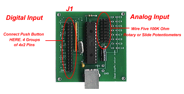
The Hilo Controller Board Below is a diagram of the Controller Board showing both Analog and Digital Input pins. The J1 connector is a 17x2 pin male header connector. This connector contains All 12 inputs where you solder your push buttons as well as the Top Hat (Coolie) switch (with your purchase, we have supplied you with SIXTEEN 2-pin female connectors and FIVE 3-pin connectors). The Digital inputs are broken down into 4 groups; Switch 1 to 4 (Group 1) - Switch 5 to 8 (Group 2) - Switch 8 to 12 (Group 3) and the Top Hat connections (Group 4). Each Group is further broken down into 4x2 pins. The Analog Inputs can be found on the right hand side of the board. These too are contained in an 8x3 pin input. The board contains 8 groups of 3 pins where you solder either a 100K Ohm Rotary or Slide Potentiometer. The board contains a male header for 8 Analog inputs, but for the 2310 and 2312 use the first 5 group of 3 pins. The remaining pins have no connection made.
|
|
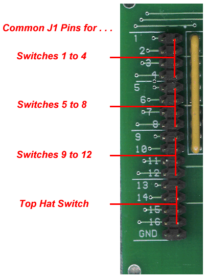
COMMON Points for Digital Switches To save on wire and soldering time, you might want to take advantage of using Common points on the board for each of the 12 Push Buttons and Coolie Switch you add to you flight sim. As mentioned above, all switches are in Groups of 4. This also holds true for the COMMON Pins on J1. From the diagram below, you can see that the COMMON Pins for Group 1 (Switches 1 to 4) are located on the right side of the J1 connector. The same holds true for Group 2, Group 3 and Group 4. NOTE: These Pins might be cadded COMMON to each Group of 4 BUT DO NOT CONNECT the Common pins of Group 1 with that of Group 2 or Group 3 ect. Each set of Common Pins are COMMON FOR THAT GROUP ONLY. Connection Common pins from other Groups will provide undesired results.
|
|
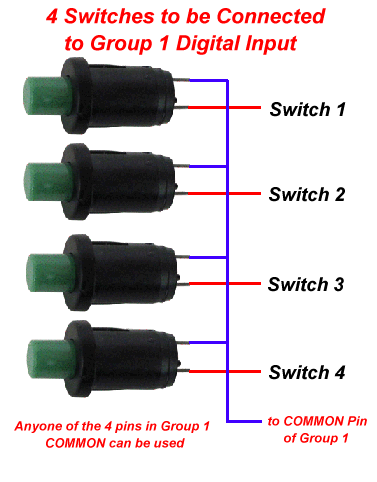
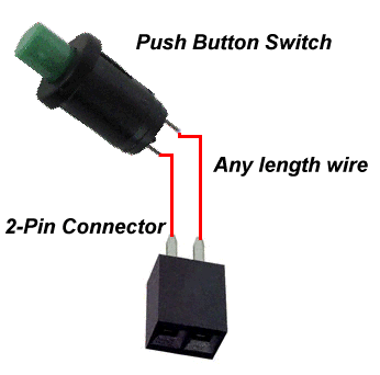
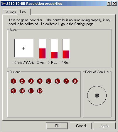
Wiring Switches using the COMMON Pins The diagram below shows how to wire 4 Spring Return Push Button Switches to Group 1 on the J1 connector using one common wire for the four. To make use of the 12 available switch inputs, just wire up 3 more assemblies as seen below, but solder the wires to the appropirate "Group". If you wish, a COMMON wire can be eliminated just by soldering 2 lengths of #24 stranded wire to the terminals of the Push button switch and the 2-pin Female Connector (provided). Then, just plug the connector to each of the J1 paired pins. (Shorting the two adjacent pins on the J1 connector will activate the appropriate "RED" balloon on the Calibration window).
Below is a diagram on how to wire each of the 12 Push Buttons to the 2-pin Female connector, if you decide not to make use of the COMMON connection
|
|
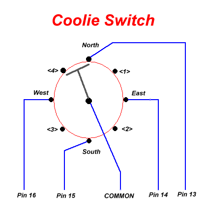
Wiring the Coolie Switch (Top Hat)
|
|
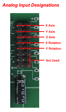
Wiring the Analog Inputs The Hilo Controller also accepts 5 analog inputs. These can be either a Rotary or Slide Potentiometer with a value of 100K Ohms. These potentiometers MUST BE called LINEAR Potentiometers. DO NOT Purchase pots called Analog as these components will give you undesired outputs. As mentioned above, ALL 5 Analog inputs MUST be connected to a potentiometer even if you do not make use of that Axis. So with that understood, below is a diagram of the 8x3 male header connectors where each potentiometer can be soldered to using the supplied 3-pin female connectors.
The X and Y Axis' are usually wired to a Joystick; this provides directional control, while the Z Axis can be used for the Throttle; X Rotation can be used to control the tail rotor's pitch and the Y Rotation can control the pitch on the main rotor assembly. |
|
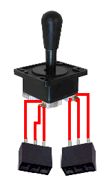
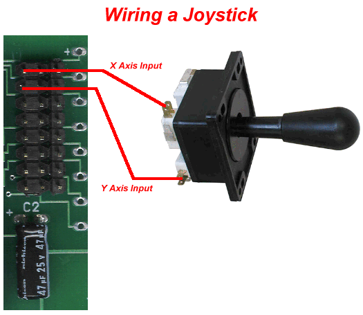
Wiring a Joystick to the Controller All Helicopters need some sort of directional control, so we can add a joystick to the Analog input X Axis and Y Axis as seen below. A Joystick assemble can be purchased just about anywhere on the internet. Just do a Google search for "Joystick Asemblies". Once you fine one, you must make sure it has a LINEAR output and its resistance for each potentiometer is about 100K ohms. If you can not find one of that value, you can go down to 10K, but no lower. If you have an old computer joystick lying around, you can take it apart and wire its internal potentiometers to the appropriate X/Y Axis on the Controller Board. Here's an idea for you, if you do not have a Joystick on hand, try going to your local Thrift or Goodwill store. I guarantee that you will find one for about $1.00 or less. Thrift stores are a treasure trove for all sorts of electronic gadgets as well as shielded RCA cables.
Wiring the LINEAR Potentiometers
So
you want to design a Throttle for your helicopter? Well, you came to the
right place. You can make your own Throttle by starting with the purchase
of a 100K Ohm Potentiometer, Make sure it is a LINEAR type. Audio taper
will not work properly. Luckly, Desktop Aviator has the Linear
Potentiometers available HERE.
To the left is a 100K Ohm
Linear Potentiometer with a short shaft (0.5in). Wiring of this pot can be
seen to the left using the supplied 3-pin female
connectors..
Wiring Slide
Assemblies
 To the left is a photo on
soldering the 3 wires from the slide to the 3 terminal
connector.
Terminal #1 from the Slide is
soldered to the Right terminal on the connector; Terminal #2 from the
Slide is soldered to the Center terminal of the connector; Terminal #3
from the Slide is soldered to the Left terminal of the
connector.
Note that the Slide has
TWO #2 terminals. This just means that these 2 terminals are connected
internally. Use the #2 terminal that is at the same end as the #3 terminal
as shown.
You can purchase the Rotary
or Slide Potentiometers. Just goto:http://www.desktopaviator.com/Products/Parts.htm
If you wish, you can purchase
your own 100K Ohm Slide Potentiometer.
Just make sure it is a "LINEAR
TYPE"; Audio Taper will not operate correctly. 10K Ohm Slides will also
work just fine.
When the wiring is complete,
just plug-in the 3-pin connectors into the Z Axis, Y rotation and X
Rotation inputs on either the 2310 or 2312 Circuit Board as seen
above.
|
|
Calibrating the Helicopter Controller Board Below is a photo of the Calibration Window from an XP computer ( the Hilo Controller will also operate in VISTA and Windows 7 computers) showing the properties of the 2030 10-Bit Resolution Helicopter controller Board. Just plug the Controller Board into an unused USB Port, your computer will sense and load the proper driver software. To get into the Calibration Window, just click on the "Start" icon located on the lower left hand corner of the screen. Then click on "Control Panel". Then on the "Games Controller" icon.
|
This Page is still Under Construction!
More to Come!
