| 
       USB to 20 Button 
      INTERFACE   
  | 
    ||||||||||||||||||||||||||||||||||||||||||||||||||||||||||||||||||||||||||||||||||||||||||||||||||||||||||||||||||
![]()  | 
    
       Best Viewed at 1024 by 768 Resolution  | |||||||||||||||||||||||||||||||||||||||||||||||||||||||||||||||||||||||||||||||||||||||||||||||||||||||||||||||||
| 
       Desktop Aviator HOME ![]() Click HERE for a LOOK at Our $$$ SAVING eBay Auctions.   
      I Accept Credit Cards Through: ![]() PAYPAL 
 
 
  | 
    
      ![]() If you have any 
      comments or need additional information on the use of the 
       
      USB to 20 Button INTERFACE, 
      please write me 
      at: 
      INSTALLATION 
      Installing the USB INTERFACE requires 
      very little time. All you need is an unused USB Port. Additional Ports can 
      be added to your computer by using a device called a USB Hub. These Hubs 
      can be purchased for as little as $20.00 in the 
      Internet. 
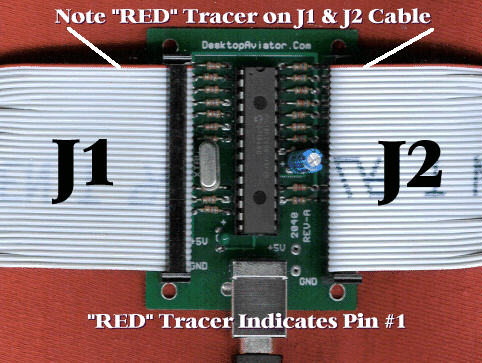
       Just plug a USB Cable Series 
      "B" into the jack on the 2040, then into the USB Port on your computer. 
      The computer will sense the Adapter and load the required software for its 
      proper operation. The 2040 will be sensed as "Digital Switch 2040". That's 
      all there is to the installation.To verify that you computer has 
      accepted the Interface, you can goto the "Game Controller" window. To do 
      this, just click on "START" (located in the lower left hand corner of the 
      computer's monitor); then click on "Control Panel"; then "Game 
      Controller". Your computer should display the 
      following: 
      ![]() Highlight 
      "Digital Switch 2040" then click "Properties" 
      ![]() The Properties Window indicates that 
      there are are 24 available switch locations, this is a mis 
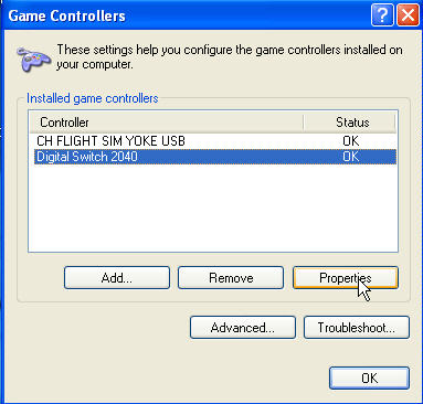
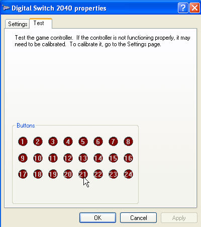
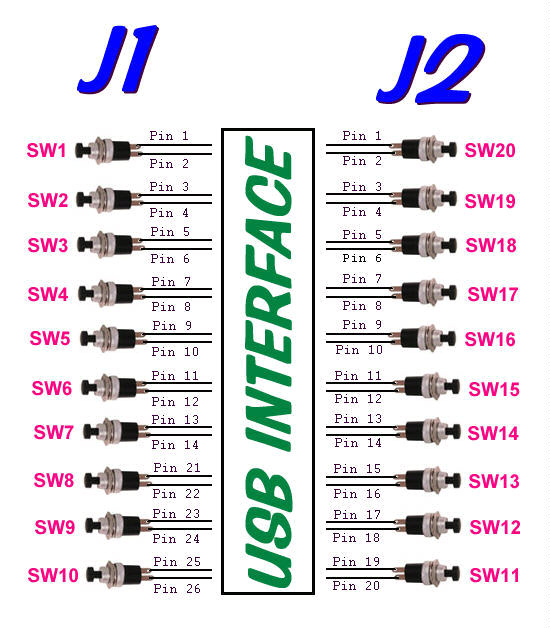
      conception. There are only 20 Buttons. The extra buttons were included in the USB Program for future expansion. Wiring Your Model 2040 USB 
      Interface 
      Below is a photo showing the 2040 
      and 2 Ribbon Cables connected to both J1 and J2 Headers. Also shown is the 
      Series "B" USB Cable. 
        The Photo seen above shows the 2 
      Ribbon Cables attached to the USB Interface. The cable on the left is 
      designated J1, while the cable on the right is J2. J1 & J2 are both 
      17x2 male "Headers" giving you 32 wires for each connector. Note the "RED" 
      tracer on each of the cables, The "RED" Tracer indicates that the wire 
      with the trace color is Position #1 (Wire 1). The second wire down is 
      Position #2; the third wire is Position #3 and so on until Wire #34 is 
      reached (last wire).  
      ![]() Push Button Switches require only 2 
      wires to operate. To make wiring of your switches as easy as 
      possible, the 2040 was designed so that 2 adjacent wires are soldered to 
      each switch. In other words, the First (Wire with RED Tracer) and the 
      Second wire soldered to a Push Button Switch (switch #1) is all that is 
      needed for your computer to sense the closure of the button. The Third and 
      Fourth wires are connected to the second Push Button Switch (switch #2). 
      The Fifth and Sixth wire are soldered to third Push Button (switch #3). Do 
      you see a pattern? 
      Wires #1 and #2 are connected to 
      Switch #1 
      Wires #3 and #4 are connected to 
      Switch #2 
      Wires #5 and #6 are connected to 
      Switch #3      And So On . . . . . 
      . 
      The Wire numbers also indicate the 
      Pin Numbers of both J1 or J2 Connectors (wire #1 is connected to Pin 1 of 
      J1 or J2 - wire #2 is connected to Pin 2 of J1 or J2 
      ect.) 
      
 
 Above is a TABLE 
      showing J1, J2 Pin assignments; their functions and what Buttons will 
      light when the switch is pressed (See "Digital Switch 2040 Properties" 
      Window - Above). 
      Lets go through a few assignments so 
      you can fully understand what's happening. With a Ribbon Cable connected 
      to the 2040 J1 Header, find the wires connected to Pins 1 and 2 (that 
      is the wire with the RED Tracer and the second from there). With the 
      "Digital Switch 2040 Properties" window showing, "short" these two wires 
      together. When shorted, the #1 Red Ball will light in the window. Remove 
      the short; the light will be extinguished. Now short the third and fourth 
      wires on the J1 Ribbon Cable. The #2 Red Button will 
      light. 
      When shorting every 2 wires, the 
      corresponding Red Button will light until you come to Pin numbers 15 and 
      16 (also can be called "Wires #15 and Wire #16). From the above TABLE, you 
      can see that Pins 15 to 20 are not connected to any circuitry. So these 6 
      Pins (or Wires) should be skipped. 
      The remaining 3 switches (Switch #8, 
      Switch #9 and Switch #10) are connected to Pins 21 & 22 - Pins 23 
      & 24 - Pins 25 & 26. The last Digital Switch on the J1 Cable is 
      #10. Pins 29/30 and Pins 33/34 are Voltage and Common Ground connections. 
      These pins come in handy if your Switch Design requires voltage to power 
      an integrated circuit, LED, small relay ect. The 5 Volt DC is present on 
      BOTH Pins 29 and 30 while the Common Ground is connected to Pins 33 and 
      34. 
      If your design requires 10 Switch or 
      less, you can stop there. But if you need more then 10 switches, you need 
      to connect a Ribbon Cable to the J2 Header and take note of the required 
      connections from the TABLE seen above. 
      If Pins 1 (Red Tracer) and 2 of the 
      J1 Cable are shorted together, the #20 Button will light. Shorting Pins 3 
      and 4 will light the #19 Button and so on until you reach Pins 21 to 34. 
      These Pins are not connected to any circuitry, so they are considered to 
      be "OPEN" Circuits. 
      Wiring the 2040 to 
      Push Button Switches 
      Now that you have an understanding on what takes 
      place on the 2040 INTERFACE, lets discuss the basics on wiring up the Push 
      Buttons. They say that "A picture is worth a thousand words", so here is 
      a diagram to show you how to wire up 20 buttons to the 
      2040. 
      ![]() The push button switches are a standard "Normally 
      Open" Spring Return type that is available at many electronic supply 
      houses on the internet. The cost ranges from between $0.27 to $0.50 
      each. 
      The Control Wires from the J1 
      Header are located at: 
      PINS 2, 4, 6, 8, 10, 
      12, 14, then starts up again at: 22, 24, 26 
      The Control Wires from the J2 
      Header are located at: 
      PINS 1, 3, 5, 7, 9, 
      11, 13, 15, 17, 19 
       HAPPY FLYING!  
      Should you require the use 
      of Toggle Switches, you may want to take a look at 
        | |||||||||||||||||||||||||||||||||||||||||||||||||||||||||||||||||||||||||||||||||||||||||||||||||||||||||||||||||